
I’ve been playing around with Arduinos and Raspberry Pis (mostly the latter) for a couple of years now. I’ve mostly been interested in producing Wi-Fi enables sensors that can measure things like temperature, and electricity usage throughout the home. I’m currently part way through a number of posts in which I have been analysing a year’s worth of data collected using some of these sensors, in the last post I dealt with a year’s worth of temperature measurements.
The connectivity problem
One of the problems I have had is finding the best way to get these sensors connected to my Wi-Fi. Let’s face it, polling sensors is not a very complex task, and in some respects a Raspberry Pi is overkill: I don’t really need a full fledged Linux computer to get temperature measurements from a couple of sensors. It would make sense to use and Arduino, a microcontroller capable of doing simple tasks more reliably. The problem is that if you want to get an Arduino to talk to the internet, you are looking at Arduino yun, Wi-Fi, or etehrnet shield, all of which are upwards of £30.
On the other hand, a Raspberry Pi zero (if you can ever get hold of one) costs just £4, but you will need to invest in a USB Wi-Fi dongle for upwards of £5. This isn’t a big outlay, but having noticed how frequently my Pis tend to miss measurements, or crash (probably due to a lack of error handling in my code), It’s left me thinking that I would have to go for an expensive in an Arduino solution.
I thought the best of both worlds might be the Raspio-duino, which is essentially an Arduino mounted on a Raspberry Pi hat. The problem here is that you still need to maintain some sort of connection between the Pi and the Arduino, and some sort of infinite loop keeping an eye on updates coming from the Arduino.
Enter the ESP8266
Recently I discovered (and a very casual glance at hackaday will show that I come very late to the party) that there is a solution to this problem in a small serial Wi-Fi board called the ESP8266. This board can add Wi-Fi connectivity to either a Raspberry Pi or an Arduino via serial, but what is really attractive about this board is that it comes with a 32bit microcontroller on board, and a number of GPIO pins - so you don’t need a separate Arduino.
In this blog post I’m documenting my first steps with the ESP8266, going from getting a board in the post to producing a super quick http server.
Where to get it
In typical fashion, the cheapest place to get these boards in China via ebay. I bought my first ESP8266 for £2.451 with a breakout board for £1.99. The latter is not essential, but does make life easier, as the board is produced at 1 mm pitch, and therefore is not breadboard friendly.
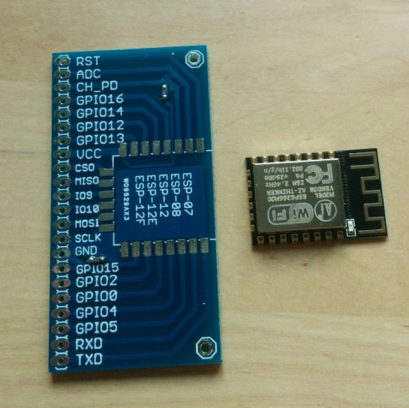
ESP8266 and breakout board
So the first job is to solder the two together. I recommend using a bit of insulation tape for the first couple of pads, just to hold everything in position.
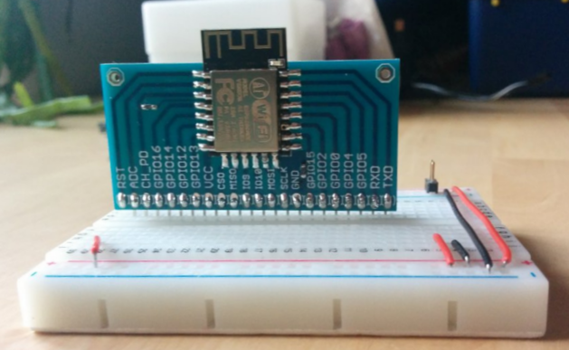 ESP8266 soldered to breakout board
One of the nice things about this breakout board that you will notice, is that there are already $10\text{k}\Omega$ surface mount resistors bridging GPIO15 to GND, and CH_PD to GPIO16. These are required if you want to talk to
Talking to the ESP8266
To get talking to the ESP8266, you will need some way of connecting via USB. There are dozens of cheap usb to serial boards on ebay based on CP210N chips. These boards typically offer 3.3v logic and 3.3v or 5v power, however cannot supply sufficient current to power the ESP8266 (which may require up to 1A), so if you are going to try to power it through the CP210N board, then use a powered hub.
Alternatively you can power the module with a separate 3.3v supply - this is what I did (actually it was 3.0v @ 1A). I did come across an instructable suggesting a mod to a CP2102 board to allow it to drive an ESP8266 by soldering a 3.3v volatage regulator across 5v and GND, and outputting this to the 3.3v pin, but I have not tried this.
It’s a little bit of a pain having to power this at 3.3v when USB runs at 5v, so it may be worth investing a little more and getting a development board which has a voltage regulator and USB-TTl onboard; you just plug in a micro usb, and you are ready to go.
The pin setup is as follows (assuming you use an external power supply like me).
| CP2102 | ESP8266 |
|---|---|
| 3.3V | _ |
| GND | GND |
| TX | RX |
| RX | TX |
If you do any reading about this module, you will see that it is quite easy to get into an infinite reset loop, the reasons for which are largely unexplained (but can be power related). I came across this post which suggested using a $470\mu\text{F}$ capacitor across the VCC and GND rails of the breadboard, and a $0.1\mu\text{F}$ capacitor from VCC to GND close to the pins on the ESP8266 breakout. These two components can help to alleviate fluctuations that can trigger seemingly unrecoverable endless resets2. Aside from potentially preventing teh endless reset loop, I found that these two capacitors improved the stability of the USB-TTL connection, without which I was generating an error every few bytes of code.
You will need a serial terminal emulator to talk to your ESP8266. I started out using the Arduino SDK serial monitor, but also tried Minicom, and gtkterm, finally settling on ESPLORER a great little Java based IDE which will run on Windows, Mac, or Linux. For me, on linux I used /dev/ttyUSB0 set to 115200 baud rate, though this may require some experimentation depending on the version of the module that you are using.
On rebooting the module, you should see:
l`rln't use rtc mem data
r##rl
Ai-Thinker Technology Co.,Ltd.

ready
Connecting to Wi-Fi
Now that the module is running, we can try to connect it to the local Wi-Fi connection. I followed the instructions here:
| Command | Response |
|---|---|
| AT | OK |
| AT+GMR | Return current firmware version of the chip |
| AT+CWLAP | List wireless access points |
| AT+CWJAP=”SSID”,”password” | Join your Wi-Fi network |
| AT+CIFSR | Return local and gateway IP address |
Flashing the module
These simple AT commands are all well and good, but if we want to do something a bit more interesting, we need to flash the chip with a more substantial language. Enter NodeMCU an open source firmware for prototyping IoT products, using the Lua language. Looking at the examples, this language looks pretty familiar, and is not difficult to get on with.
First we need to flash this firmware onto the module. I used the excellent NodeMCU custom builds to create a customised .bin file, which you can very simply download3.
Then I tied GPIO to ground to enter the flash mode, and used a python script available on github to flash the binary. I used the code:
sudo ./esptool.py -p /dev/ttyUSB0 -b 921600 write_flash 0x00000 ~/Dropbox/NodeMCU/nodemcu-master-8-modules-2016-01-30-18-30-32-float.bin
to flash the binary to position 0x00000 at a baud rate of 921600. The -p flag sets the device, which will tend to be /dev/ttyUSB0.
If all goes to plan, when you remove the GPIO-GND wire and reboot the module (by crossing RST to GND momentarily) you should be greeted with:
NodeMCU custom build by frightanic.com
	branch: master
	commit: c8037568571edb5c568c2f8231e4f8ce0683b883
	SSL: false
	modules: file,gpio,net,node,ow,tmr,uart,Wi-Fi
 build 	built on: 2016-01-30 18:29
 powered by Lua 5.1.4 on SDK 1.4.0
Connecting to Wi-Fi with Lua
We can then get the module to connect to Wi-Fi using Lua using:
=Wi-Fi.sta.config("SSID","password")
and get the IP address with:
=Wi-Fi.sta.getip()
If I now scan my local network, I can see the device has connected to my router’s access point, and has an IP address, in this case: 192.168.1.167. If I do a port scan however, there are no open ports.
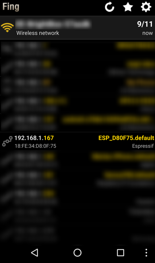 Running a network scan using Fing
A simple Lua http server
Taking one of the examples from the NodeMCU homepage, I used ESPLORER to run the following code on the ESP8266 module.
-- a simple http server
srv=net.createServer(net.TCP)
srv:listen(80,function(conn)
    conn:on("receive",function(conn,payload)
    print(payload)
    conn:send("<h1> Hello, NodeMCU.</h1>")
    end)
end)
Then I ran a portscan again. Sure enough, port 80 on 192.168.1.167 appeared open.
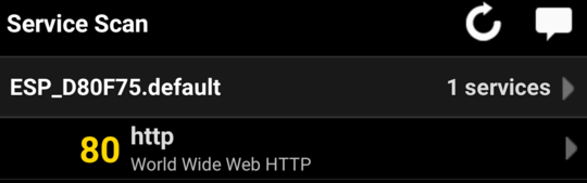
Results from a port scan show just one open port: 80, corresponding to the port we opened with the code snippet above.
When I opened it with a browser I got the simple message Hello, NodeMCU.
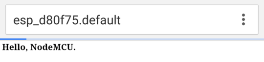
The view from chrome on my phone when accessing the Wi-Fi module. We get back the code <h1> Hello, NodeMCU.</h1> rendered as a webpage.
Looking back to the console I have kept open, I can see the http GET request being sent by my browser.
> GET / HTTP/1.1
Host: 192.168.1.167
Connection: keep-alive
Accept: text/html,application/xhtml+xml,application/xml;q=0.9,image/webp,*/*;q=0.8
Upgrade-Insecure-Requests: 1
User-Agent: Mozilla/5.0 (X11; Linux x86_64) AppleWebKit/537.36 (KHTML, like Gecko) Chrome/48.0.2564.82 Safari/537.36
Accept-Encoding: gzip, deflate, sdch
Accept-Language: en-US,en;q=0.8
Next steps
So with a small amount of fiddling, I’ve been able to get the ESP8266 module working as an http host. My next step is to start to get the module talking to sensors through the GPIO pins. OneWire is supported, so getting it to talk to ds18b20 temperature sensors should be a pretty simple affair.
After that, two things remain:
- How to deal with time. Will it be necessary to connect a Real Time Clock (RTC) module, or is it possible to get time from a web service? Do I need to do both?
- How do I get the data recorded from a sensor into the Postgres database I use for my sensor readings.
In the former, I need to do a bit of reading. For the latter, I’m planning on building a RESTful API for the database, (possibly using postgrest) which will allow me to make http PUT commands to insert the data without fuss.
This can even be achieved relatively simply with nginx.
Useful resources
- http://www.instructables.com/id/Using-the-ESP8266-module/?ALLSTEPS
- http://www.instructables.com/id/Getting-Started-with-the-ESP8266-ESP-12/?ALLSTEPS
- http://nodemcu.com/index_en.html
- https://learn.adafruit.com/adafruit-huzzah-esp8266-breakout/using-nodemcu-lua
-
Note that I have used the ESP8266 ESP12F module. If you look for the older versions ESP1 for instance, these can be a little bit cheaper, and still provide very similar functionality. ↩
-
I actually didn’t have a $0.1\mu\text{F}$ capacitor, so used a $1\mu\text{F}$ instead, and it seems that stability of the terminal connection has been improved nonetheless. ↩
-
The site will give you two
.binfiles - one for integer and one for floats. I’m interested in taking temperature readings with a ds18b20 temperature sensor, so I will need to be able to handle floats, but the integer bin is slightly smaller (I assume this is the difference, as it is not too transparent). ↩